Autonomy Hardware Assembly For Spark
The Completetion of the Autonomy Hat hardware development
Recap
It has been a month or so since my last update on this project. During this time I was able to finalize the hardware and get it to a point where I am simply doing software finally!! Here are the highlights of the months and the process.
The Initial Assembly
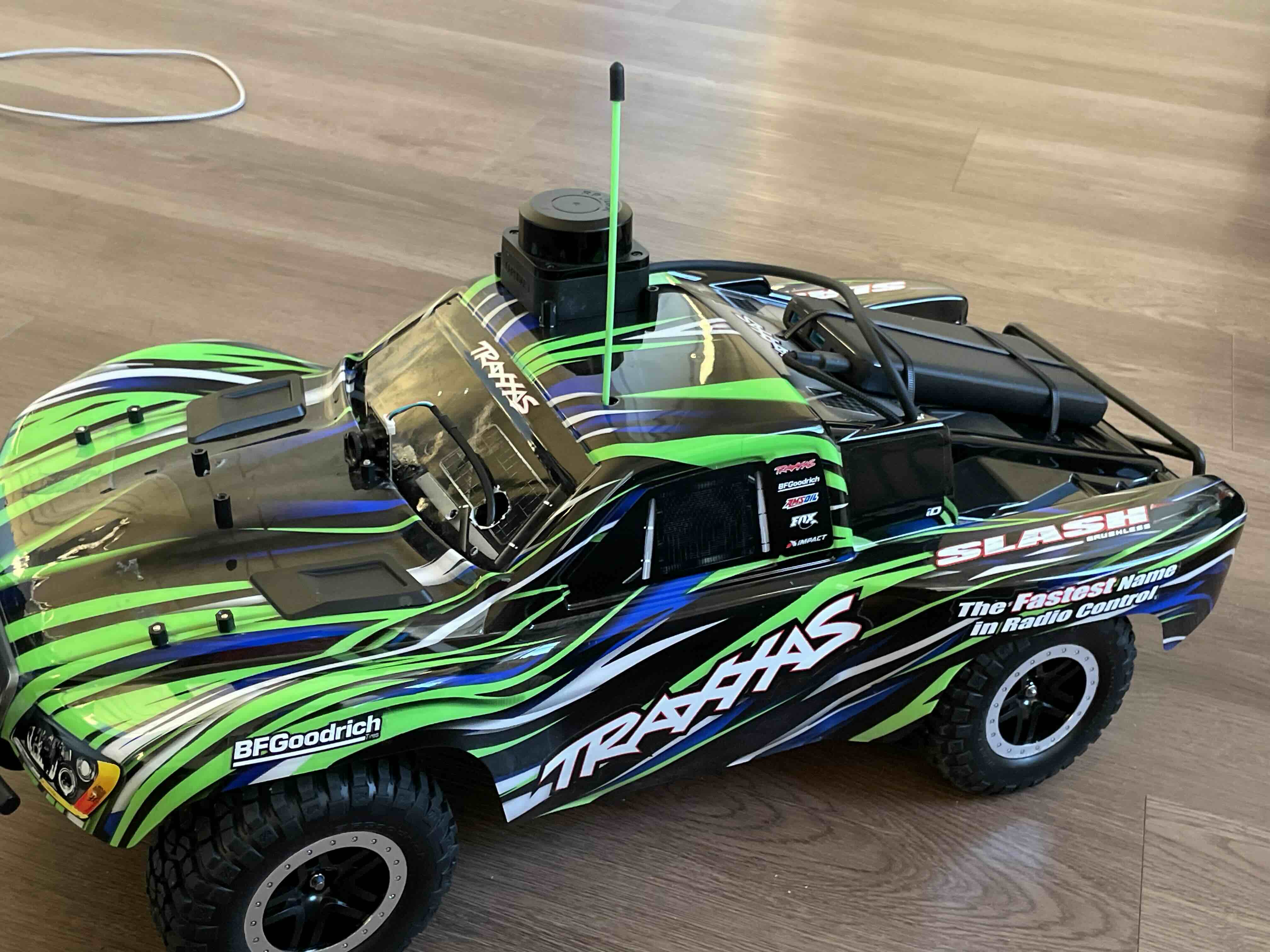
So the big idea here was to utilize the plastic body shell that is typically clipped on the rc car as the structure to hold all the components. While not the best plan structurally speaking, this was the fastest way to get components on the car. Besides whats the worst that could happen?
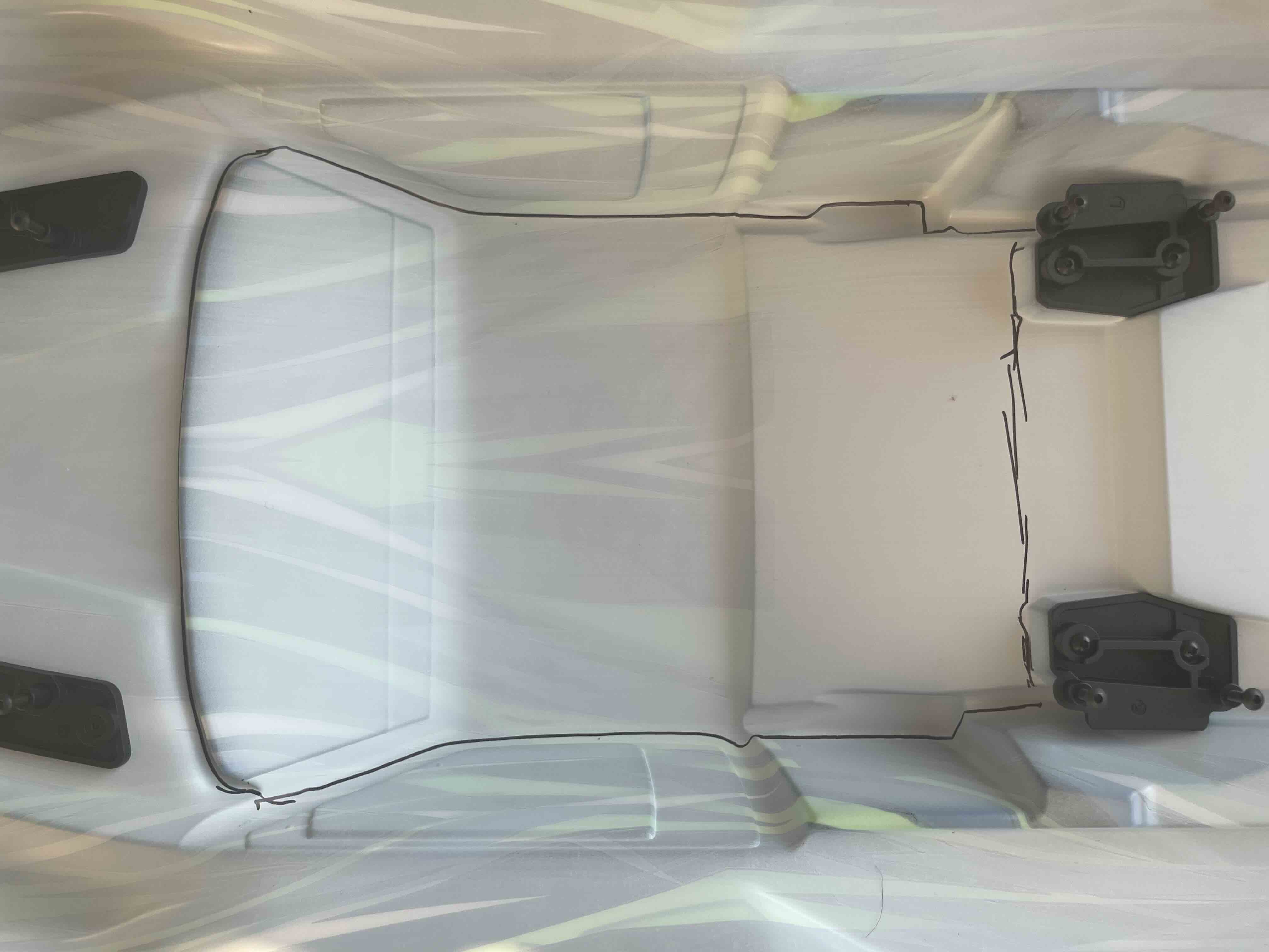 Figure 1: The space I was working with
I started by taking some measurements of the body and started to plan how I would compose the several components that would make up the autonomy system. I had to figure out how to mount: a RaspberryPi; 3 Google Coral Tpus; Usb Extender; Lidar; Camera; and a powerbank for control power. I also got the antenna extended so that the signals from the remote would be able to be recieved with little electrical interference. Originally, I was going to plan this all out in CAD or something but I decided against this since CAD is a pain for me.
Mounting holes
So I just kinda started cutting stuff. I went to the Lowes next door and picked up a dremel and starting going to town as they say. I ended up just making a bunch of holes for mounting the battery and the wires that go from the camera, lidar and battery to the processor. For example here is what the battery mounts looked like once I was done:
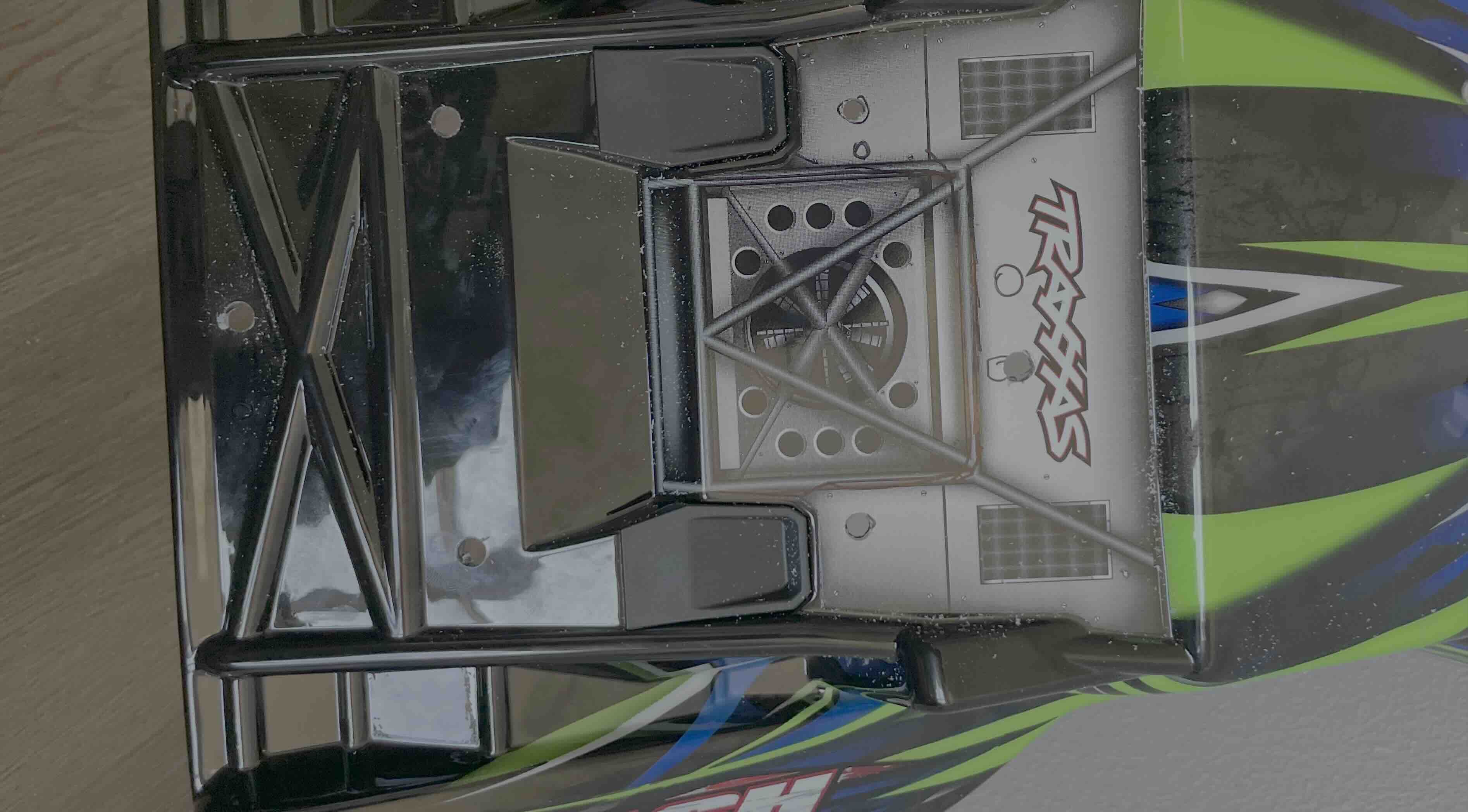 Figure 2: The holes for mounting the battery
I did not end up taking many picturs of the patterns that I drilled into the body as I was doing this but I am sure the idea is clear. I put a component on the car and then drill the mounting holes for it into the body and hope I don’t break the body or the component. Hardware is so much fun.
TPU & Compute Bay
Once the holes were done, it was time to start mounting the RasberryPi and the TPUs that would actually bring this project to life. I ended up putting the TPUs all in the front since they were relatively light and I did not want them to take away too much space from the center of the body. I ended up going with a triangle like pattern aswell because it allowed me to wire them all in a managable way. I then added the USB extender and the RaspberryPi to the body and tested to see if the connections were good and if I could see the TPUs. By the time this was done, the sun had set so I got to see what it looked like in the dark.
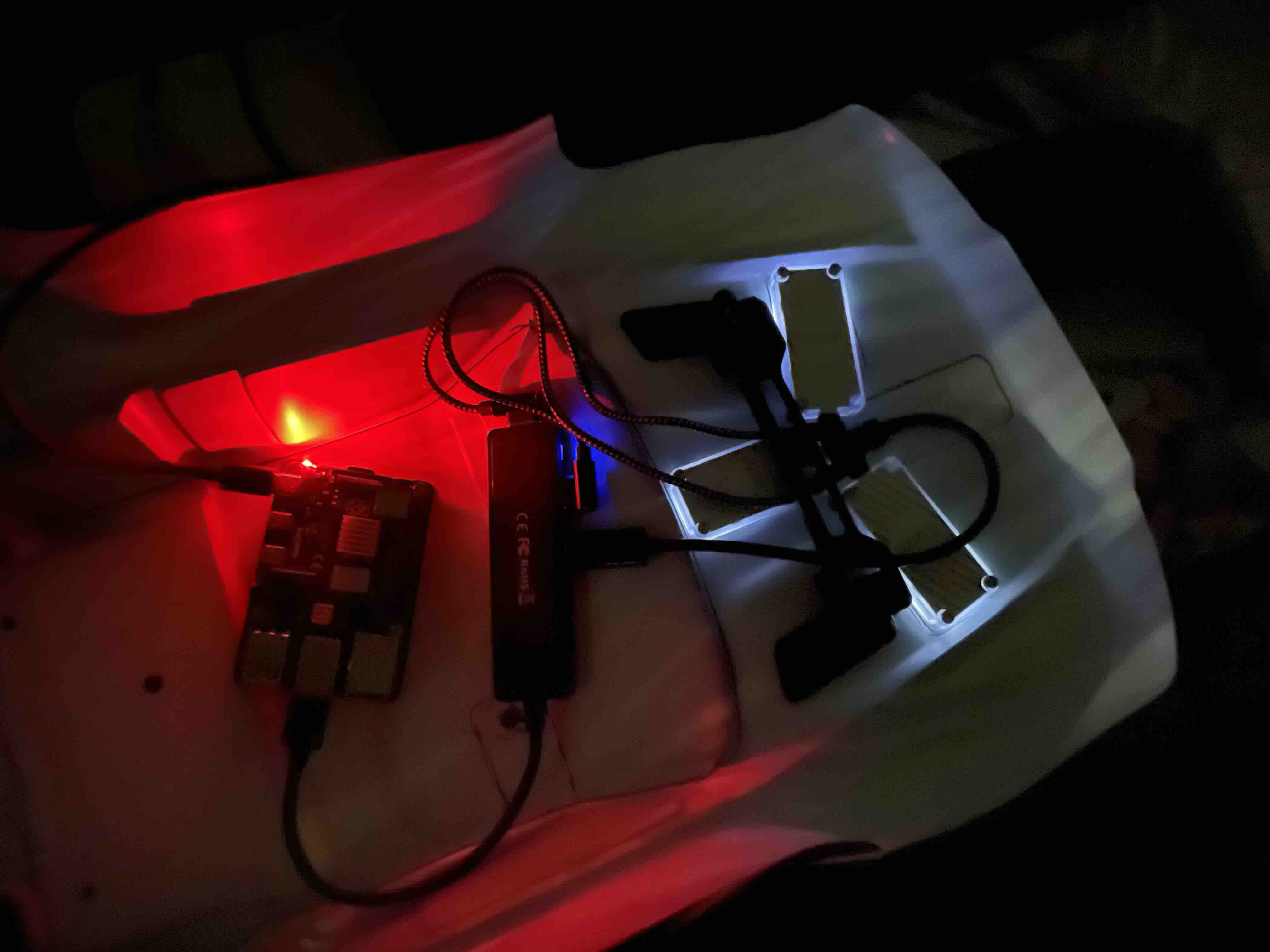 Figure 3: Testing the TPU Configuration
Now I can’t just have these components floating around inside of the body since they would be effectively upside down when mounted on the car so I used some screws and electrical tape.
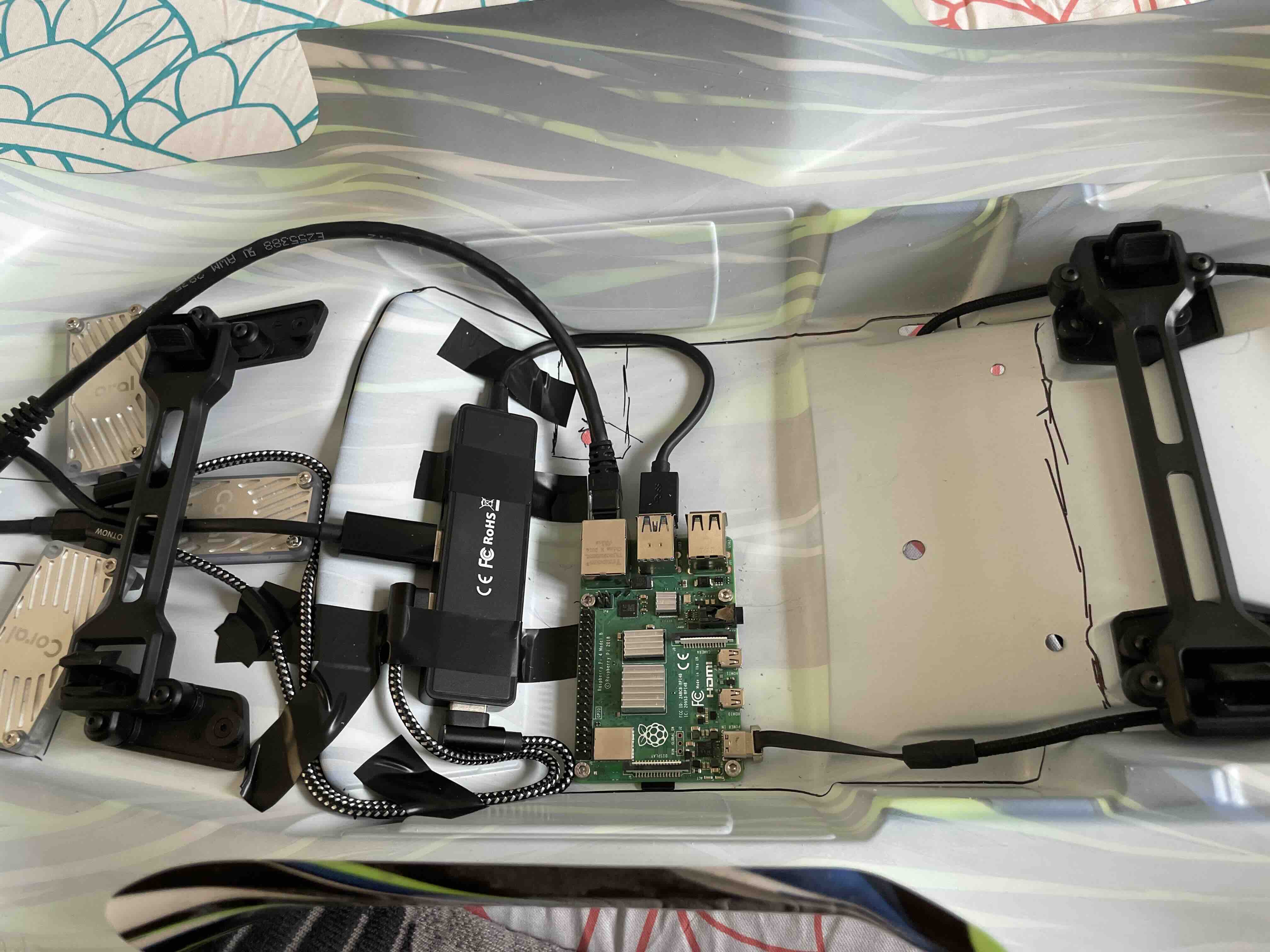 Figure 3: Testing the TPU Configuration
I then tested this with the battery to see if this configuration worked, which thankfully it did!! Since this was good, it was time to start putting some sensors on this car.
Mounting the Rest
Now I did not really take any pictures during this process since I forgot to, but this was the order of operations. First came the lidar. The lidar was basically superglued onto the roof which seems to be solid for the time being and the wires were ran to through the same hole that was made for the power cable. Next up was the camera, for which I also used super glue. While the mounting was probably not the best, it so far has managed to hold up for the time being. I also ended up drilling a hole in the window to let the wires for the camera pass through. Finally I used 4 zipties to mount the battery to the body.
Figure 4: Final Assembly?
Small Mods
Once I had finished the assembly, I realized a few issues.
For one, the RaspberryPi was pressed to the body too tightly which resulted in me breaking a micro sdcard. To remedy this I added some standoffs to make the micro sd card more accessible. I also cut a rectangle on the side of the car to let me switch sd cards easily. The next change I made was adding an ethernet port to the car so that way I could connect the car to my computer easily.
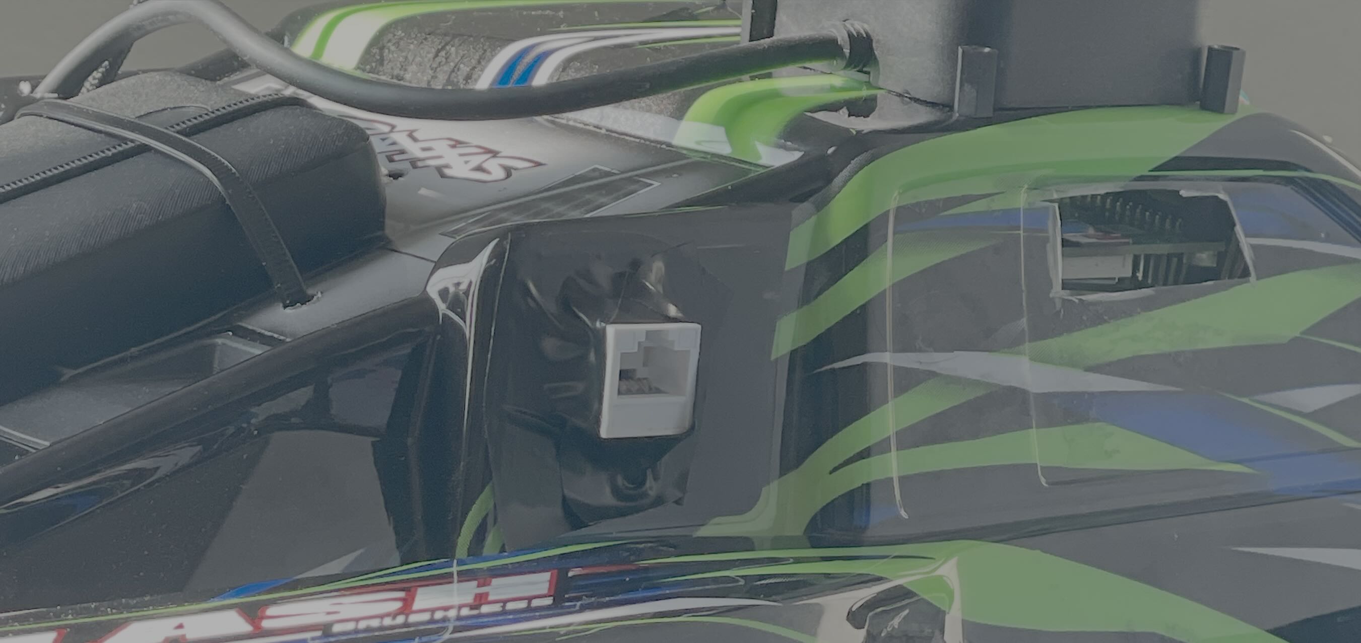 Figure 5: Accessiblity Changes
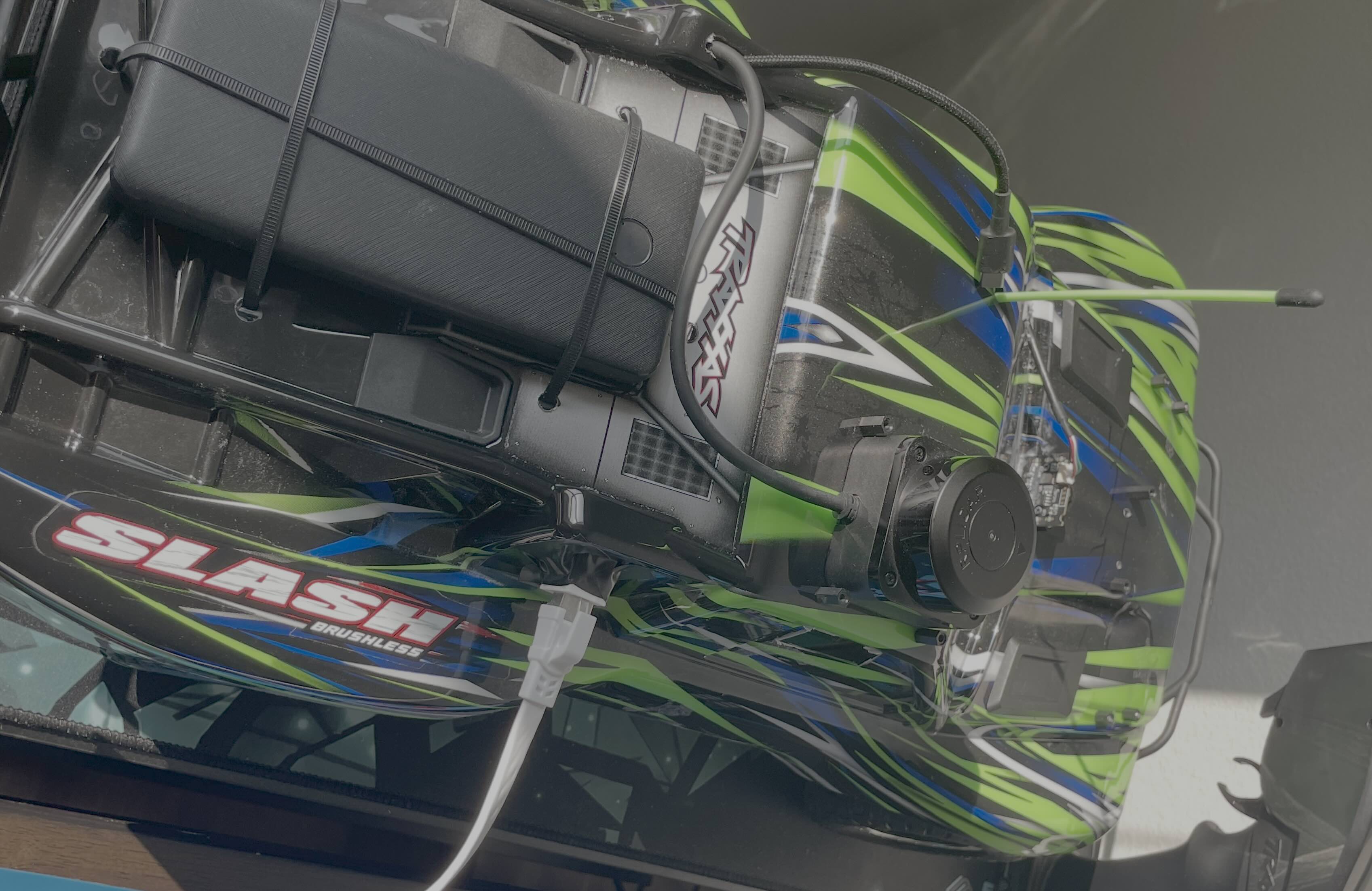 Figure 6: Accessiblity Changes
With these changes, this was the final wiring layout inside the body:
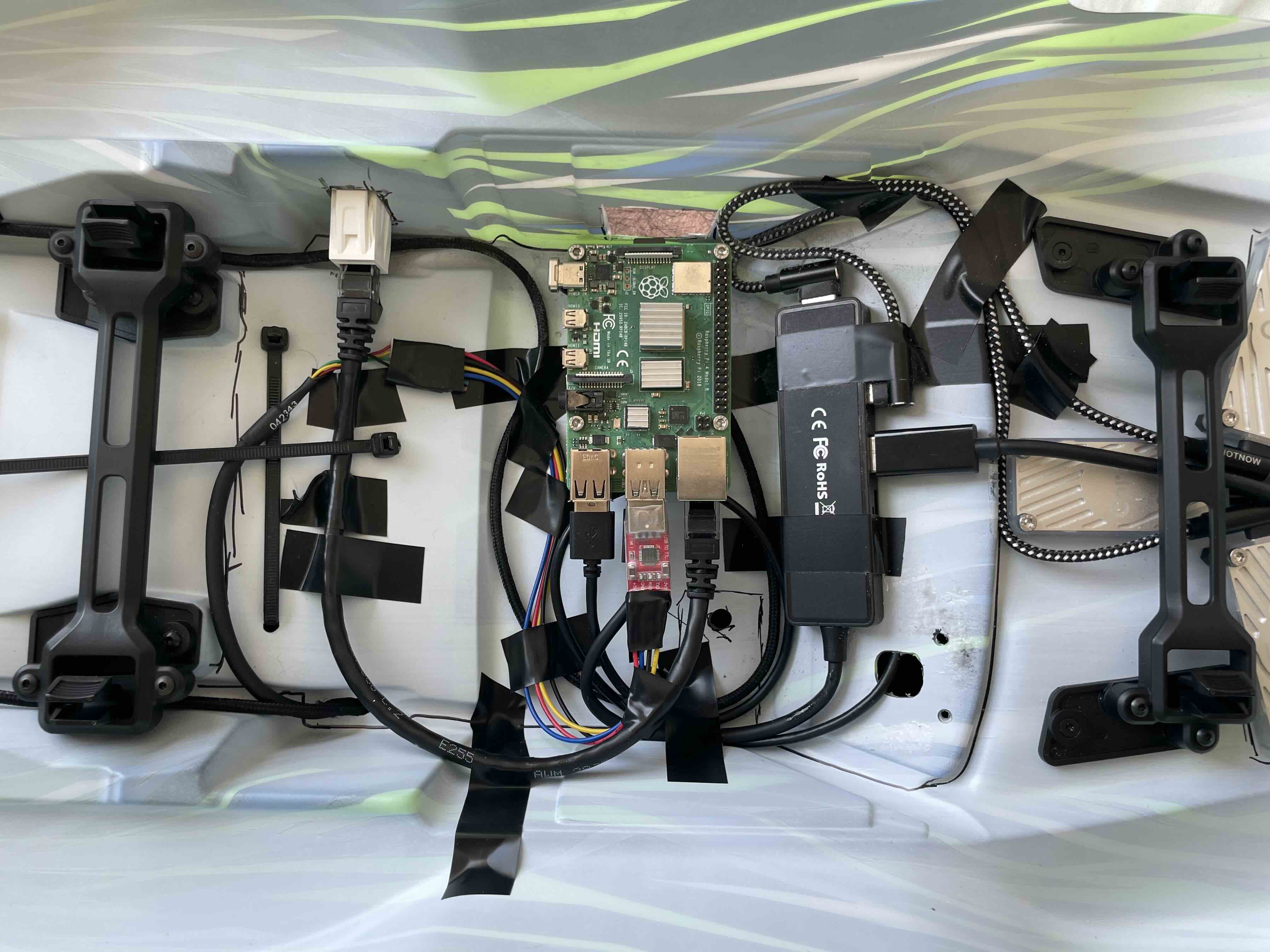 Figure 7: Wiring Layout
Next Steps
Now that the hardware is all done, it is finally time to do some software!!